MECHANICAL PROPERTIES OF CABLE TRAY
A) SAFE WORKING LOAD
When in use, the cable management system has to support the weight of the cables and other complementary
products. The products safe working load test values according to IEC 61537 help adapt the best installation
configuration
Safe working load (SWL) is the maximum load which can be applied safely during normal cable management use.
While testing, gradually increasing loads are applied to the cable management system. This uniformly distributed
load is expressed in daN/m .
The safe working load obtained guarantees:
• A maximum longitudinal deflection of 1/100th of the span (example: 20 mm deflection for a distance between
supports of 2000 mm)
• A maximum horizontal deflection of 1/20th of the cable tray width (example: 10 mm deflection for a cable tray
width of 200 mm)
• A safety coefficient of 1.7.
There are three types of tests: They are mainly distinguished by the location of the coupling in the span
• Type 1: A connector shall be located in the middle of the first span. Associated mounting recommendation: this
is the most restrictive configuration, which can offer a guarantee of safe loads in the installation without any
conditions.
![]()
• Type 2: : A connector shall be located in the middle of the second span. Associated mounting recommendation:
to guarantee safe loads, the installation should not contain a coupling in an end span.
![]()
• Type 3: The position of the connector is fixed, the length of the tested cable tray must be a multiple of the span.
Associated mounting recommendation: the installation should comply with the manufacturer’s recommended
coupling location.
![]()
NEMA VE-1 is a cable management standard which has evolved in parallel with IEC 61537 but drafted by a North
American electrical committee. The standard specifies the manufacturing requirements for metal cable trays and
provides load/span class designations. It also stipulates requirements and test methods for cable tray systems
with aim to declare the required load capacity.The test is conducted on the cable management system uniformly
loaded between two supports.

Destructive method: This involves continuing until the system collapses. The load chosen for the SWL is then
the collapse load divided by a safety factor of 1.5.
Support Span: Strength of a cable tray system is largely determined by the strength of its side rails. The
strength of a side rail is proportionate to the distance between the supports on which it is installed, commonly
referred to as ‘support span’. Therefore, strength of a cable tray system can be changed by modifying support
span. The support span length should be equal or less than uncoupled straight section lengths to ensure that no
more than one splice is placed between the supports
B) DEFLECTION
All profiles deflect when a load is imposed. The deflection of cable tray is related to applied load, support span,
size and material of beam and load. Deflection tests are carried out according to IEC 61537.
C) IMPOSED LOADS
Imposed loads include wind, ice and snow. The effects of imposed loads will vary from one installation to another
and further advice relating to the specific influences of each should be sought at the design stage. The following
information on imposed loads is given as a general guide only.
Snow loads: The additional design load from snowfall should be determined using the building codes that apply
for each installation
Ice loads: The additional load design due to the ice is determined by the following formula:
Wi = W x Ti x Di/106
Where:
Wi = ice load (kg/m)
W = width of the tray (mm)
Ti = maximum ice thickness (mm)
Di = 913 kg/m³ – ice density
Ice thickness will vary depending on installation location. A value of ½” (12.7mm) can be used as a
conservative standard.
Wind Loads: The additional loading to be considered is the effect of the impact pressure vertical to the side rail.
This loading is determined by the following formula:
Wp = 0.00256 x V2 x H/12
Where:
Wp = loading due to the wind (lbs/linear foot)
V = wind velocity (mph)
H = height of the side rail (inch)
Seismic loads: It is now known that cable tray systems can withstand stronger earthquakes than previously
thought. The tray itself and the support material are highly ductile, and the cables moving within the tray tend to
dissipate energy. However, if you have specific seismic specifications for selected cable tray, please consult Kıraç
Metal team to ensure your specifications are met.
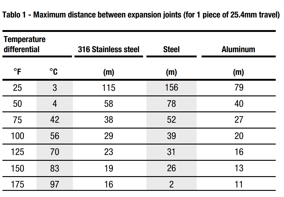
D) THERMAL EXPANSION AND CONTRACTION
A cable tray system may be affected by thermal expansion and contraction, which must be taken into account
during installation. To determine the number of expansion splice plates you need, decide the length of the straight
cable tray runs and the total difference between the minimum winter and maximum summer temperatures. To
function properly, expansion splice plates require accurate gap settings between trays. To find the gap (see Figure
1).
To plot the gap setting:
• Locate the lowest metal temperature on min. temperature line.
• Locate the highest metal temperature on max. temperature line.
• Connect these two points.
• Locate installation temperature and plot to high/low line.
• Drop plot to gap setting.
